Arduino project “bathroom window”
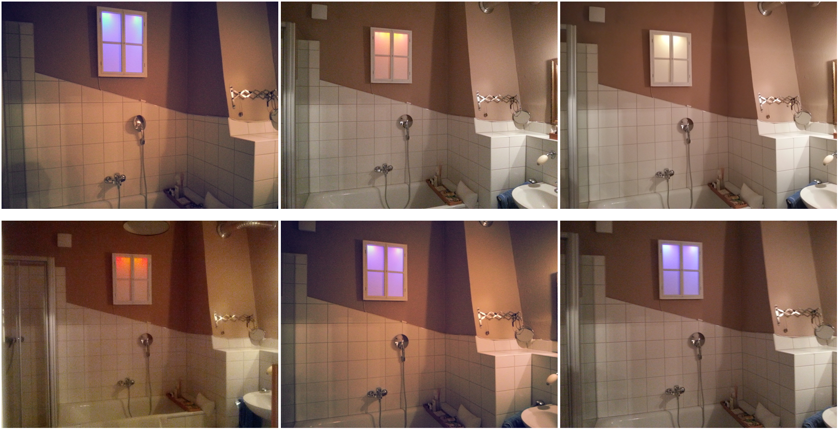
This tutorial describes the building of a fake window which is illuminated by superlight LEDs in different colors. These are controlled by an Arduino microcontroller board so that the current daytime is reflected by the light mood.
Please contact me
for questions and tips or corrections of this tutorial! I’m no pro, and I’m
aware that a couple of things could be optimized. Please send me pictures and experiences of your window project!
Video of the demo mode, 3 sec = 1 hour.
Video starts at about 4am, sunrise after 7 seconds:
Material (with links to German stores for pictures):
- Electronics:
o 16 superlight LEDs, 5mm: http://www.reichelt.de/LEDs-super-ultrahell/2/index.html?;ACTION=2;LA=3;GROUPID=3019
§ 4 * LED 5-05000 BL
§ 4 * LED 5-14000 GE
§ 4 * LED 5-16000 RT
§ 4 * LED 5-16000 WW
o 16 * Montage clips for LEDs 5mm: http://www.reichelt.de/LED-Zubehoer/MONTAGERING-5MM/3//index.html?ACTION=3&GROUPID=3044&ARTICLE=12529&SHOW=1&START=0&OFFSET=16&
o ULN 2803A (Transistor array): http://www.reichelt.de/ICs-U-ZTK-/ULN-2803A/3/index.html?;ACTION=3;LA=446;ARTICLE=22085;GROUPID=2921;artnr=ULN+2803A
o Mains adapter:
§ either wall wart: http://www.reichelt.de/Festspannungsnetzteile/SNT-600-12V/3//index.html?ACTION=3&GROUPID=4946&ARTICLE=108294&SHOW=1&START=0&OFFSET=16&
§ or an in-built power supply circuit (I took the interior of a wall wart…)
o Resistors
o Wires, breadboard
o Arduino Uno Board
- Plexi glass, 3mm: http://www.plexiglas-shop.com/DE/de/details.htm?$product=c4vxotqb32k~p&$category=8ny276huqre
- Fake window frame: http://www.maisonsdumonde.com/UK/en/produits/fiche/seaside-window-picture-122855.htm
- Wood bars, MDF plate, screws
- non-flammable diffuser foil (or just take the inner Kellogg’s cereal bag: http://www.masterpaklb.com/pictures/products/Products_0.5697308_cereal-bags-header.jpg)
- aluminum wrap
Steps:
1. Arduino programming:
The main program is basically three lines of code (lines 100-103).
I included the Arduino time library (see code line 4) that offers me the current time after calibrating it in the setup (line 65). The current daytime between 0 and 24 is in the variable uhrzeit (line 100).
Now where is the light mood saved? The two-dimensional const int array ledmat carries the info about the desired light mood at several daytimes (lines 13-44). It contains 10 vectors which carry the levels of the 4 LED colors in dB from -20(Off) to 0(full brightness), the overall level and the corresponding daytime at which these levels apply. For example, the third vector in line 21 {-5,-2,-20,-10,0,7 } determines that at 7:00h we have -5dB white, -2dB yellow, no red and -10dB blue with a full overall level of 0dB.
Now we need a translation between the current daytime and the array index so that we can look up in ledmat. For this the routine get_stundenindices is called (line 102) which tells you the array index corresponding to the last daytime at which a vector applied (hourindex) and the array index corresponding to the next daytime at which a vector applied (hourindex_next). On top of that it tells you where in between these two daytimes we actually are by the variable fade. For example, at 6:30h in the morning we are half way between vector 1 (6.00; line 19) and vector 2 (7:00; line 22), so hourindex=1 and hourindex_next=2 with fade=0.5.
The next step is already the LED writing in the routine writeLEDs (line 103). This routine looks the relevant parameters up in the array ledmat using the indices calculated before. With the fade parameter the LED levels are linearly interpolated between the defined values corresponding to the daytime. The translation between the logarithmical dB values and the correct 0-255 int value that analogWrite expects is done in the routine ledpegel. We’re done.
I need to say I run a demo loop in fast motion (a day in 1.5 minutes) just after starting the program in the setup part, so that I can show off to my visitors ;) The video of this demo loop is shown above.
|
Arduino Badfenster Code
(click for download) |
1 /*Badfenster:
steuert 16 LEDs an, abhängig von der Tageszeit
2 */
4 #include <Time.h>
6 //Konstanten
7 const int
ledweiss = 3;
8 const int
ledgelb = 5;
9 const int
ledrot = 6;
10 const int
ledblau = 9;
11 const int
del=5000;
12 const int
hourindex_anzahl = 10;
13 const int
ledmat[hourindex_anzahl][6]={
14 //weiss,gelb,rot,blau,Gesamtpegel,Zeitpunkt(Stunden)
15 {
16 -20,-20,-20,0,0,0}
17 ,
18 {
19 -20,-20,-20,0,0,6 }
20 ,
22 -5,-2,-20,-10,0,7 }
23 ,
24 {
25 0,-8,-20,-20,0,10 }
26 ,
27 {
28 0,-20,-20,-20,0,12}
29 ,
30 {
31 0,-20,-20,-20,0,16}
32 ,
33 {
34 0,0,-20,-20,0,17}
35 ,
36 {
37 -10,0,0,-20,0,18}
38 ,
39 {
40 -20,-20,-10,0,0,20}
41 ,
42 {
43 -20,-20,-20,0,0,22}
44 };
46 //Variablen
47 float uhrzeit;
48 float t=0;
49 float fade;
50 int hour_aktuell;
51 int hour_next;
52 int hourindex;
53 int hourindex_next;
54 int ledmatschaltzeiten[hourindex_anzahl+1];
56 // the setup routine runs once when you press
reset:
57 void setup() {
58 Serial.begin(9600); // open the serial port at 9600 bps:
59 //
initialize the digital pin as an output.
60 pinMode(ledweiss, OUTPUT);
61 pinMode(ledgelb, OUTPUT);
62 pinMode(ledrot, OUTPUT);
63 pinMode(ledblau, OUTPUT);
65 setTime(8,45,0,1,1,2013); //Hier wird die Startzeit gesetzt: setTime(hr,min,sec,day,month,yr);
66 for (int i=0;i<hourindex_anzahl;i++){
67 ledmatschaltzeiten[i]=
ledmat[i][5];
68 }
69 ledmatschaltzeiten[hourindex_anzahl]=24;
71 //Nach Einschalten zunächst eine oder mehrere
Demoschleifen:
72 for (int durchlauf=0;durchlauf<1;durchlauf++){
73 for
(float h=0;h<24;h=h+0.025){
74 uhrzeit=h;
75 get_stundenindices(&uhrzeit,&hour_aktuell,&hour_next,&hourindex,&hourindex_next,&fade);
76 writeLEDs(&hourindex,&hourindex_next,&fade);
77 //delay(1);
78 Serial.print("DEMO-Modus:
");
79 Serial.print(uhrzeit);
80 Serial.print(",
hourindex: ");
81 Serial.print(hourindex);
82 Serial.print("--");
83 Serial.print(hourindex_next);
84 Serial.print(",
fade: ");
85 Serial.print(fade);
86 Serial.print(",
hour: ");
87 Serial.print(hour_aktuell);
88 Serial.print("--");
89 Serial.print(hour_next);
90 Serial.println();
91 }
92 }
93 }
95 // the loop routine runs over and over again
forever:
96 void loop()
{
98 //Zeit
99 //
uhrzeit=(float(hour())+float(minute())/60+float(second())/3600)*60*12;//Zeitraffer zum Testen
100 uhrzeit=(float(hour())+float(minute())/60+float(second())/3600);
102 get_stundenindices(&uhrzeit,&hour_aktuell,&hour_next,&hourindex,&hourindex_next,&fade);
103 writeLEDs(&hourindex,&hourindex_next,&fade);
105 //Test-Ausgabe
106 Serial.print(hour());
107 Serial.print(":");
108 Serial.print(minute());
109 Serial.print(":");
110 Serial.print(second());
111 Serial.print(",
uhrzeit: ");
112 Serial.print(uhrzeit);
113 Serial.print(",
hourindex: ");
114 Serial.print(hourindex);
115 Serial.print("--");
116 Serial.print(hourindex_next);
117 Serial.print(",
fade: ");
118 Serial.print(fade);
119 Serial.print(",
hour: ");
120 Serial.print(hour_aktuell);
121 Serial.print("--");
122 Serial.print(hour_next);
123 Serial.println();
125 //Warten...
126 delay(del);
129 int ledpegel(float pegel1,float pegel2) {
130 float
abspegel1=pow(10,pegel1/10);
131 float
abspegel2=pow(10,pegel2/10);
132 float abspegel=abspegel1*abspegel2;
133 if (abspegel<=0.011)
134 {
135 abspegel=0;
136 }
137 if (abspegel>1)
138 {
139 abspegel=1;
140 }
141 int pegel=int(255*abspegel);
143 // Serial.print(abspegel);
144 // Serial.print("\t");
145 // Serial.print(pegel);
146 // Serial.print("\t");
148 return pegel;
151 void get_stundenindices(float
*uhrzeit, int *hour_aktuell, int *hour_next, int *hourindex, int *hourindex_next, float *fade) {
152 //Stunden-Indices
153 for (int i=0;i<hourindex_anzahl;i++) {
154 if (*uhrzeit>=ledmatschaltzeiten[i]
&& *uhrzeit<ledmatschaltzeiten[i+1])
{
155 *hour_aktuell=ledmatschaltzeiten[i];
156 *hour_next=ledmatschaltzeiten[i+1];
157 *hourindex=i;
158 *hourindex_next=i+1;
159 if
(*hourindex_next>=hourindex_anzahl){
160 *hourindex_next=0;
161 }
162 }
163 }
164 *fade=(*uhrzeit-*hour_aktuell)/(*hour_next-*hour_aktuell);
167 void writeLEDs(int *hourindex,int *hourindex_next,float *fade)
169 float pegel[5];
170 int pegelweiss=0;
171 int pegelgelb=0;
172 int pegelrot=0;
173 int pegelblau=0;
175 //LEDPegel
176 pegel[0]=ledmat[*hourindex][0]*(1-*fade)+ledmat[*hourindex_next][0]*(*fade);
177 pegel[1]=ledmat[*hourindex][1]*(1-*fade)+ledmat[*hourindex_next][1]*(*fade);
178 pegel[2]=ledmat[*hourindex][2]*(1-*fade)+ledmat[*hourindex_next][2]*(*fade);
179 pegel[3]=ledmat[*hourindex][3]*(1-*fade)+ledmat[*hourindex_next][3]*(*fade);
180 pegel[4]=ledmat[*hourindex][4]*(1-*fade)+ledmat[*hourindex_next][4]*(*fade);
181 pegelweiss=ledpegel(pegel[0],pegel[4]);
182 pegelgelb=ledpegel(pegel[1],pegel[4]);
183 pegelrot=ledpegel(pegel[2],pegel[4]);
184 pegelblau=ledpegel(pegel[3],pegel[4]);
186 //write
LEDs
187 analogWrite(ledweiss, pegelweiss);
188 analogWrite(ledgelb, pegelgelb);
189 analogWrite(ledrot, pegelrot);
190 analogWrite(ledblau, pegelblau);
192 Serial.print("Pegel: ");
193 Serial.print(pegel[0]);
194 Serial.print(",");
195 Serial.print(pegel[1]);
196 Serial.print(",");
197 Serial.print(pegel[2]);
198 Serial.print(",");
199 Serial.print(pegel[3]);
200 Serial.print(",");
201 Serial.print(pegel[4]);
202 Serial.print("
- ");
2. Circuitry
I produced a small circuitry on a breadboard that will fit directly behind the MDF strip that carries the LEDs. I lost my sketch, sorry, if anyone does this project please post the circuit here again J However, the circuit is very, very easy: it only contains the ULN 2803A Transistor array and 16 resistors as well as wire connections from the Arduino board and to the 16 LEDs. Each of the 4 AnalogWrite outputs of the Arduino board (defined in line 7-10) was connected to two inputs of the ULN 2803A. 8 outputs of the ULN 2803A were used. Each of them was connected to two LEDs and two resistors. Hence, each two LEDs were either in parallel or in serial. Calculate the necessary resistors so that the 5V is divided and the correct voltage is on the LEDs. Note that the 4 LED colors have different operation voltages and currents! The 5V for LEDs and ULN 2803A and the ground for the ULN 2803A is connected from the Arduino board. After finishing the circuit, connect the LEDs with wires enough long to fit the LED mounting bar (see below).
3. Wood frame
- Build the back plate: this is an MDF plate or a flake board with exactly the same length and width as the window frame which you build on your own or bought from e.g. : http://www.maisonsdumonde.com/UK/en/produits/fiche/seaside-window-picture-122855.htm
- Build four wood bars as upper, lower, left and right “walls” of your window frame. Their sizes:
a) For left and right wall bars: length= the height of the window frame, width: about 5-6 cm, minimum the width of your breadboard!, depth: so that a screw fits in, ca. 15mm.
b)
For upper and lower wall bars: length=the width
of the window frame minus 2*the bar depth, width and depth, as above.
The upper bar gets two rectangular holes for the USB and Power input of the Arduino board.
- Build an LED mounting bar (thin MDF plate): same size as b) above, but with low depth.
o Drill holes for the 16 LED clips in equal distances into it.
o Cut some space for the Arduino bar in one corner of the LED mounting bar, it will be placed right above it.
o Put the LED montage clips into the LED mounting bar
o Put the LEDs into the clips. I used the following order of colors: b – r – b – r – y – w – y – w – w – y – w – y – r – b – r – b
- Connect the upper and lower bars to the MDF plate as with screws through the MDF or glue as can be seen in the pictures. Leave space for the left and right bars.
- Mount the breadboard on the upper wall bar somehow, I used two little screws.
- Mount the Arduino board with little screws on the MDF plate
- Connect the LED mounting bar with 4 screws to the upper wall bar
-
Optional: connect the Arduino
Voltage in and ground with the output of your power supply circuit. Mount the
Power supply circuit somewhere and lead the mains cable out of the frame (small
extra hole in one of the wall bars).
You don’t have to do this. If you simply want to connect a wall wart to the
Power input socket of the Arduino, you’re fine (even better in the bathroom!)
Now the frame is nearly ready, as you see it in the pictures. Sorry that I haven’t taken more pictures, I wasn’t thinking about writing a DIY tutorial…
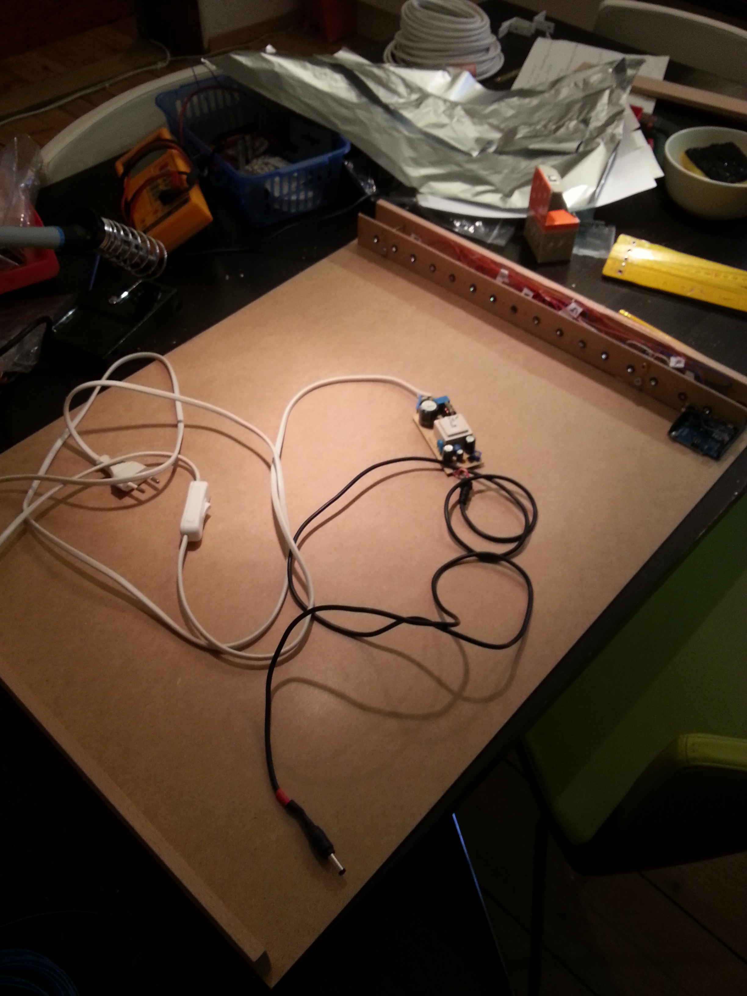
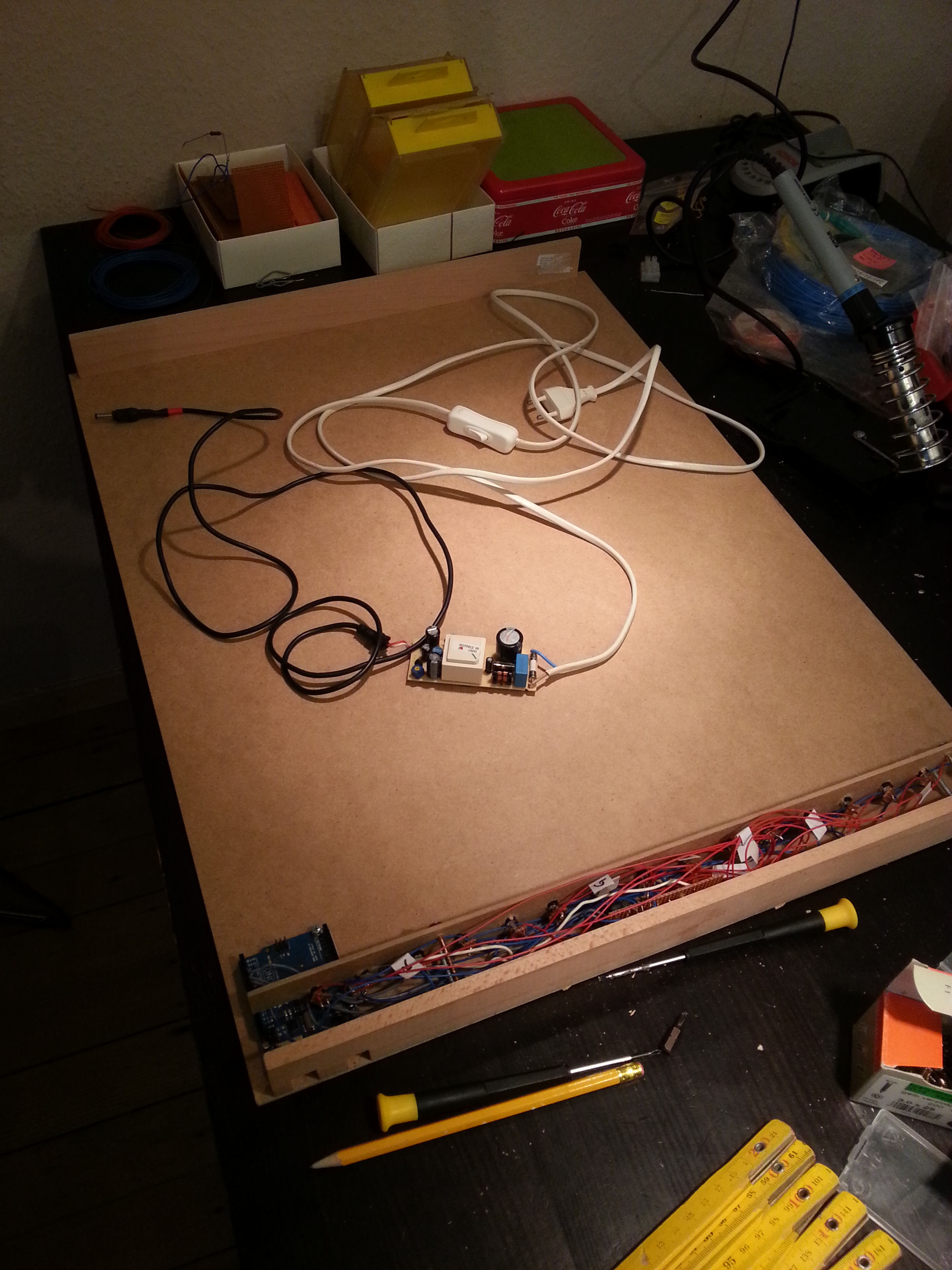
Now, for a better light performance, glue aluminum wrap on the surface of the whole MDF plate. Then put diffuser foil or alike in a loose bow on the LED mounting bar, so that the LED light is diffused. Don’t forget to mount some wall mounting thing at the back of the MDF plate! Now the whole MDF/circuit part is ready.
Now we produce the window frame part. Replace the ugly picture from the fake window frame with a fitting milky plexi glass and mount it. The plexi glass I used is 3mm thick, see above’s link. Mount the left and right wall bars onto the window frame (screw or glue) and optionally paint the whole thing. Now this part is ready as well and the “marriage” happens:
Put the window frame part on top of the MDF/circuit part and mount it (screws!). Ready.
Well, now just program and fine-tune the Arduino! Please contact me for questions and tips or corrections of this tutorial!

Btw, this is the evening original lightmood in my hometown: